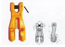
sling accessories
1: All forged by alloy steel
2: heat treatment processed by arts of heat treatment
3: small size, high strength |
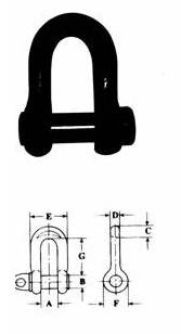
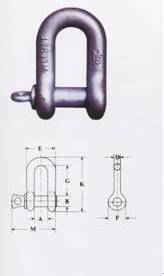
D-shackle (international standard)
working load limit |
A |
B |
C |
D |
E |
F |
G |
TON |
mm |
mm |
mm |
mm |
mm |
mm |
mm |
0.3 |
16 |
10 |
|
8 |
|
|
45 |
0.5 |
20 |
12 |
|
10 |
40 |
23 |
50 |
0.9 |
24 |
16 |
|
12 |
48 |
29 |
60 |
1.4 |
32 |
20 |
|
16 |
64 |
38 |
80 |
2.1 |
36 |
24 |
|
20 |
76 |
46 |
90 |
2.7 |
40 |
27 |
|
22 |
80 |
48 |
100 |
3.3 |
45 |
30 |
|
24 |
95 |
58 |
110 |
4.1 |
50 |
33 |
|
27 |
106 |
63 |
120 |
4.9 |
58 |
36 |
|
30 |
118 |
70 |
130 |
6.8 |
64 |
42 |
|
36 |
136 |
77 |
150 |
9.5 |
70 |
50 |
|
40 |
150 |
90 |
170 |
10.7 |
80 |
52 |
|
45 |
170 |
97 |
190 |
16 |
100 |
64 |
|
52 |
204 |
120 |
204 |
20 |
105 |
65 |
72 |
52 |
225 |
120 |
218 |
25 |
110 |
70 |
72 |
52 |
226 |
130 |
238 |
30 |
115 |
76 |
80 |
55 |
235 |
135 |
260 |
32 |
125 |
80 |
90 |
60 |
261 |
145 |
310 |
40 |
125 |
86 |
96 |
64 |
265 |
155 |
315 |
50 |
132 |
96 |
107 |
72 |
292 |
175 |
330 |
60 |
135 |
103 |
117 |
78 |
307 |
185 |
366 |
75 |
145 |
106 |
120 |
80 |
325 |
190 |
392 |
80 |
166 |
112 |
126 |
84 |
345 |
200 |
438 |
100 |
176 |
123 |
141 |
94 |
384 |
225 |
473 |
140 |
190 |
145 |
165 |
110 |
430 |
265 |
520 |
150 |
196 |
148 |
186 |
120 |
456 |
270 |
543 |
200 |
246 |
165 |
195 |
130 |
526 |
300 |
628 |
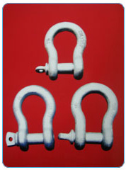
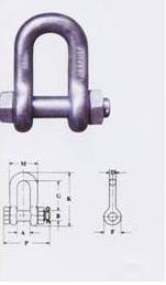
American standard bow type shackle (G210)
type |
rated load |
A |
B |
D |
E |
F |
G |
K |
M |
weight |
in |
Ton |
mm |
mm |
mm |
mm |
mm |
mm |
mm |
mm |
kg |
1/4 |
0.50 |
12.0 |
7.9 |
6.4 |
23.9 |
15.5 |
22.4 |
40.4 |
35.1 |
0.05 |
5/16 |
0.75 |
13.5 |
9.7 |
7.9 |
29.5 |
19.1 |
26.2 |
48.5 |
42.2 |
0.08 |
3/8 |
1.00 |
16.8 |
11.2 |
9.7 |
35.8 |
23.1 |
31.8 |
58.4 |
51.6 |
0.13 |
7/16 |
1.50 |
19.1 |
12.7 |
11.2 |
41.4 |
26.9 |
36.6 |
67.6 |
60.5 |
0.20 |
1/2 |
2.00 |
20.6 |
16.0 |
12.7 |
45.0 |
30.2 |
41.4 |
77 |
68.3 |
0.27 |
5/8 |
3.25 |
27.0 |
19.0 |
16.0 |
58.7 |
38.1 |
50.8 |
95.3 |
84.8 |
0.57 |
3/4 |
4.75 |
31.8 |
22.4 |
19.1 |
69.9 |
46.0 |
60.5 |
115.1 |
100.8 |
1.9 |
7/8 |
6.50 |
36.6 |
25.4 |
22.4 |
81.0 |
53.1 |
71.4 |
135.4 |
114.8 |
1.43 |
1 |
8.50 |
43.0 |
28.7 |
25.4 |
93.7 |
60.5 |
81.0 |
150.9 |
128.8 |
2.15 |
11/8 |
9.50 |
46.0 |
31.8 |
28.7 |
103.1 |
68.3 |
90.9 |
172.2 |
142.0 |
3.06 |
11/4 |
12.0 |
51.6 |
35.1 |
31.8 |
115.1 |
76.2 |
100.1 |
190.5 |
156.5 |
4.14 |
13/8 |
13.5 |
57.2 |
38.1 |
35.1 |
127.0 |
94.1 |
111.3 |
210.3 |
173.7 |
5.28 |
11/2 |
17 |
60.5 |
41.4 |
38.1 |
136.6 |
91.9 |
122.2 |
230.1 |
186.7 |
7.23 |
13/4 |
25 |
73.2 |
50.8 |
44.5 |
162.1 |
106.4 |
146.1 |
278.6 |
230.6 |
12.13 |
2 |
35 |
82.6 |
57.2 |
50.8 |
184.0 |
122.2 |
171.5 |
311.9 |
262.6 |
19.19 |
21/2 |
55 |
105.0 |
69.9 |
66.5 |
238.3 |
144.5 |
203.2 |
376.9 |
330.2 |
32.55 |
American standard bow type shackle (2150)
type |
Rated
load |
A |
B |
D |
E |
F |
G |
K |
M |
weight |
in |
Ton |
mm |
mm |
mm |
mm |
mm |
mm |
mm |
mm |
kg |
1/2 |
2 |
20.6 |
16.0 |
12.7 |
30.2 |
41.4 |
77.0 |
46.1 |
71.1 |
0.34 |
5/8 |
3.25 |
26.9 |
19.1 |
16.0 |
38.1 |
50.8 |
95.3 |
58.7 |
89.7 |
0.67 |
3/4 |
4.75 |
31.8 |
22.4 |
19.1 |
45.0 |
60.5 |
115.1 |
70.0 |
103.4 |
1.14 |
7/8 |
6.50 |
36.6 |
25.4 |
22.4 |
53.1 |
71.4 |
135.4 |
81.0 |
119.6 |
1.75 |
1 |
8.5 |
42.9 |
28.7 |
25.4 |
60.5 |
81.0 |
150.9 |
93.7 |
134.9 |
2.52 |
11/8 |
9.5 |
46.0 |
31.8 |
28.7 |
38.6 |
90.9 |
172.2 |
103.1 |
149.9 |
3.45 |
11/4 |
12.0 |
51.6 |
35.1 |
31.8 |
76.2 |
100.0 |
190.5 |
115.1 |
165.4 |
4.90 |
13/8 |
13.5 |
57.2 |
38.1 |
35.1 |
84.1 |
111.3 |
210.3 |
127.0 |
183.1 |
6.24 |
11/2 |
17.0 |
60.5 |
41.4 |
38.1 |
92.2 |
122.2 |
230.1 |
136.7 |
196.3 |
8.39 |
13/4 |
25.0 |
73.2 |
50.8 |
44.5 |
106.4 |
146.1 |
278.6 |
162.1 |
229.8 |
14.24 |
2 |
35 |
82.6 |
57.2 |
50.8 |
122.2 |
171.5 |
311.9 |
184.2 |
264.4 |
21.20 |
21/2 |
55 |
104.9 |
70.0 |
66.5 |
144.5 |
203.2 |
377.0 |
238.3 |
344.4 |
38.56 |
3 |
85 |
127.0 |
82.6 |
76.2 |
165.1 |
215.9 |
428.8 |
279.4 |
419.1 |
56.36 |
31/2 |
120 |
133.4 |
95.3 |
91.9 |
203.2 |
- |
- |
- |
482.6 |
- |
4 |
150 |
139.7 |
108.0 |
104.1 |
228.6 |
- |
- |
- |
501.7 |
- |
American standard bow type shackle (209)
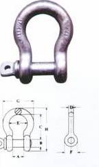
Type |
Rated
load |
A |
B |
C |
D |
E |
F |
G |
H |
weight |
in |
Ton |
mm |
mm |
mm |
mm |
mm |
mm |
mm |
mm |
kg |
3/16 |
0.33 |
9.7 |
6.4 |
22.4 |
4.8 |
15.2 |
14.2 |
24.9 |
37.3 |
0.03 |
1/4 |
0.50 |
11.9 |
7.9 |
28.7 |
6.4 |
19.8 |
15.5 |
32.5 |
46.7 |
0.05 |
5/16 |
0.75 |
13.5 |
9.7 |
30.9 |
7.9 |
21.3 |
19.1 |
37.3 |
53.1 |
0.09 |
3/8 |
1.0 |
16.8 |
11.2 |
36.6 |
9.7 |
26.2 |
23.1 |
45.2 |
63.2 |
0.14 |
7/16 |
1.5 |
19.1 |
12.7 |
42.9 |
11.2 |
29.5 |
26.9 |
51.6 |
73.9 |
0.17 |
1/2 |
2.0 |
20.6 |
16.0 |
47.8 |
12.7 |
33.3 |
30.2 |
58.7 |
83.3 |
0.33 |
5/8 |
3.25 |
26.9 |
19.1 |
60.5 |
16.0 |
42.9 |
38.1 |
74.7 |
106.4 |
0.62 |
3/4 |
4.75 |
31.8 |
22.4 |
71.4 |
19.1 |
50.8 |
46.0 |
88.9 |
126.2 |
1.07 |
7/8 |
6.50 |
36.6 |
25.4 |
84.1 |
22.4 |
57.9 |
53.1 |
102.4 |
148.1 |
1.64 |
1 |
8.5 |
42.9 |
28.7 |
95.3 |
25.4 |
68.3 |
60.5 |
119.1 |
166.6 |
2.28 |
11/8 |
9.5 |
45.0 |
31.8 |
108.0 |
29.5 |
73.9 |
68.3 |
131.1 |
189.7 |
3.36 |
11/4 |
12.0 |
51.6 |
35.1 |
119.1 |
32.8 |
82.6 |
76.2 |
146.1 |
209.6 |
4.31 |
13/8 |
13.5 |
57.2 |
38.1 |
133.4 |
36.1 |
92.2 |
84.1 |
162.1 |
232.7 |
6.14 |
11/2 |
17.0 |
60.5 |
41.4 |
146.1 |
39.1 |
98.6 |
92.2 |
174.8 |
254.0 |
7.80 |
13/4 |
25.0 |
73.2 |
50.8 |
177.8 |
46.7 |
127.0 |
106.4 |
225.0 |
314.4 |
12.60 |
2 |
35 |
82.6 |
57.2 |
196.9 |
52.8 |
146.1 |
122.2 |
253.2 |
347.5 |
20.41 |
21/4 |
55 |
104.9 |
69.9 |
266.7 |
68.8 |
184.2 |
144.5 |
326.9 |
453.1 |
38.90 |
American standard bow type shackle (2130)
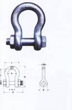
type |
Rated load |
A |
B |
C |
D |
E |
F |
H |
L |
P |
weight |
in |
Ton |
mm |
mm |
mm |
mm |
mm |
mm |
mm |
mm |
mm |
kg |
1/2 |
2 |
20.6 |
16.0 |
47.8 |
12.7 |
33.3 |
30.2 |
83.3 |
58.7 |
71.1 |
0.36 |
5/8 |
3.25 |
26.9 |
19.1 |
60.5 |
16.0 |
42.9 |
38.1 |
106.4 |
74.7 |
89.7 |
0.76 |
3/4 |
4.75 |
31.8 |
22.4 |
71.4 |
19.1 |
50.8 |
45.0 |
126.2 |
88.9 |
103.4 |
1.23 |
7/8 |
6.50 |
36.6 |
25.4 |
84.1 |
22.4 |
57.9 |
53.1 |
148.1 |
102.4 |
119.6 |
1.79 |
1 |
8.5 |
42.9 |
28.7 |
95.3 |
25.4 |
68.3 |
60.5 |
166.9 |
119.1 |
134.9 |
2.57 |
11/8 |
9.5 |
46.0 |
31.8 |
108.0 |
28.7 |
73.9 |
68.3 |
189.7 |
131.1 |
149.9 |
3.75 |
11/4 |
12.0 |
51.6 |
35.1 |
119.1 |
31.8 |
82.6 |
76.2 |
209.6 |
146.1 |
165.4 |
5.31 |
13/8 |
13.5 |
57.2 |
38.1 |
133.4 |
35.1 |
92.2 |
84.1 |
232.7 |
162.1 |
183.1 |
7.18 |
11/2 |
17.0 |
60.5 |
41.4 |
140.1 |
38.1 |
98.6 |
92.2 |
254.0 |
174.8 |
196.3 |
9.43 |
13/4 |
25.0 |
73.2 |
50.8 |
177.8 |
44.5 |
127.0 |
106.4 |
313.4 |
225.0 |
229.8 |
15.38 |
2 |
35 |
82.6 |
57.2 |
196.9 |
50.8 |
146.1 |
122.2 |
347.5 |
253.2 |
264.4 |
23.70 |
21/2 |
55 |
104.9 |
70.0 |
266.7 |
66.5 |
184.2 |
144.5 |
453.1 |
326.9 |
344.4 |
44.57 |
3 |
85 |
127.0 |
82.6 |
330.2 |
76.2 |
200.2 |
165.1 |
546.1 |
364.7 |
419.1 |
69.85 |
31/2 |
120 |
133.4 |
95.3 |
371.6 |
91.9 |
228.6 |
203.2 |
625.6 |
419.1 |
482.6 |
120.2 |
4 |
150 |
139.7 |
108.0 |
368.3 |
104.1 |
254.0 |
228.6 |
652.5 |
467.9 |
501.7 |
153.32 |
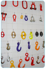
Goat horns slide hook
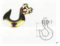
chain diameter
in |
Rated load |
A |
B |
C |
D |
Weight |
H-331 |
A-331 |
in |
in |
in |
in |
Lbc/pc |
1/4 |
1950 |
2750 |
0.44 |
0.94 |
0.38 |
2.56 |
0.50 |
5/16 |
2870 |
4300 |
0.50 |
1.06 |
0.44 |
2.87 |
0.75 |
3/8 |
4000 |
5250 |
0.59 |
1.31 |
0.47 |
3.25 |
1.20 |
7/16 |
5000 |
7000 |
0.66 |
1.56 |
0.56 |
3.70 |
2.06 |
1/2 |
6500 |
9000 |
0.75 |
1.69 |
0.63 |
4.00 |
2.80 |
5/8 |
9250 |
13500 |
0.91 |
2.00 |
0.75 |
4.94 |
4.75 |
3/4 |
12500 |
19250 |
1.31 |
2.50 |
1.00 |
6.09 |
10.30 |
Goat horns slide hook (with insurance card )
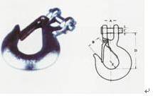
chain diameter
in |
Rated load |
A |
B |
C |
D |
E |
Weight |
H-331 |
A-331 |
in |
in |
in |
in |
in |
Lbc/pc |
1/4 |
1950 |
2750 |
0.44 |
0.79 |
0.38 |
2.56 |
0.79 |
0.52 |
5/16 |
2870 |
4300 |
0.50 |
0.93 |
0.44 |
2.87 |
0.79 |
0.77 |
3/8 |
4000 |
5250 |
0.59 |
1.14 |
0.47 |
3.25 |
1.02 |
1.23 |
7/16 |
5000 |
7000 |
0.66 |
1.18 |
0.56 |
3.70 |
1.03 |
2.10 |
1/2 |
6500 |
9000 |
0.75 |
1.42 |
0.63 |
4.00 |
1.38 |
2.85 |
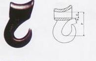
Goat horns hoist
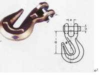
specification |
Rated load |
A |
B |
C |
D |
Weight |
H-331 |
A-331 |
in |
in |
in |
in |
Lbc/pc |
1/4 |
2600 |
3600 |
0.36 |
0.94 |
0.40 |
1.97 |
0.40 |
5/16 |
3900 |
5400 |
0.40 |
1.06 |
0.44 |
2.26 |
0.79 |
3/8 |
5400 |
7500 |
0.48 |
1.31 |
0.47 |
2.63 |
1.00 |
7/16 |
7200 |
10000 |
0.66 |
1.56 |
0.56 |
2.75 |
1.50 |
1/2 |
9200 |
12750 |
0.75 |
1.69 |
0.63 |
3.19 |
2.10 |
5/8 |
12750 |
19000 |
0.91 |
2.00 |
0.75 |
4.09 |
4.20 |
3/4 |
16500 |
27000 |
0.94 |
2.50 |
0.88 |
4.63 |
6.50 |
Goat horns slide hook with forged tongue

| specification |
Weight(kg) |
wllT |
Breaking load T |
7/8-8 |
0.52 |
2 |
8 |
10-8 |
0.96 |
3.2 |
12.8 |
13-8 |
1.90 |
5.4 |
21.6 |
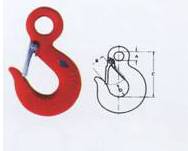
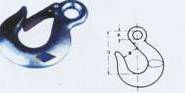
eye slip hook
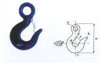
Workingload limit |
A |
B |
C |
D |
E |
F |
R |
ton |
mm |
mm |
mm |
mm |
mm |
mm |
mm |
0.5 |
120 |
40 |
10 |
28 |
16.0 |
22.0 |
8 |
1 |
155 |
48 |
16 |
37 |
22.40 |
31.5 |
9.2 |
2 |
170 |
60 |
25 |
37 |
25.0 |
32.0 |
11 |
3 |
230 |
78 |
32 |
55 |
35 |
42.5 |
14 |
5 |
270 |
92 |
40 |
60 |
42 |
50.0 |
20 |
8 |
298 |
98 |
40 |
65 |
46 |
55.0 |
20 |
10 |
330 |
110 |
45 |
77 |
52 |
63 |
22 |
15 |
460 |
160 |
70 |
115 |
110 |
80 |
40 |
37 |
630 |
210 |
110 |
140 |
110 |
95 |
35 |
S hook
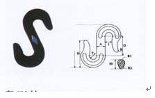
| Rated load |
T |
A |
B |
D |
J |
R |
R1 |
R2 |
H |
H1 |
Weight |
ton |
mm |
mm |
mm |
mm |
mm |
mm |
mm |
mm |
mm |
mm |
Kg/pc |
1 |
25 |
25 |
166 |
75 |
24 |
7 |
11 |
6 |
97 |
33 |
1 |
2 |
28 |
28 |
175 |
80 |
26 |
8 |
12 |
7 |
106 |
33.5 |
1.5 |
3 |
30 |
30 |
183 |
80 |
30 |
9 |
13 |
8 |
117 |
36.5 |
2 |
5 |
44 |
44 |
243 |
100 |
38 |
12 |
16.5 |
10 |
158 |
49.5 |
4.5 |
180 |
60 |
60 |
311 |
125 |
55 |
17 |
20 |
12 |
196 |
63 |
8 |
10 |
75 |
75 |
361 |
150 |
70 |
18 |
21 |
12.5 |
240 |
68 |
12 |
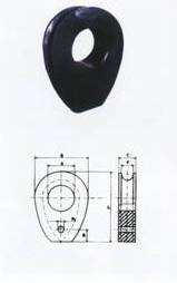
nose-shaped hook
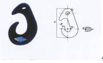
| Rated load |
A |
B |
C |
D |
E |
R |
ton |
mm |
mm |
mm |
mm |
mm |
mm |
1 |
170 |
21 |
21 |
34 |
22 |
6 |
2 |
208 |
25 |
25 |
40 |
30 |
8 |
3 |
253 |
31 |
31 |
60 |
35 |
10 |
5 |
303 |
38 |
38 |
70 |
45 |
13 |
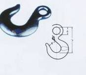
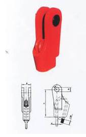
straight shank hook

Rated load |
X |
K |
F |
J |
Y |
G |
ton |
mm |
mm |
mm |
mm |
mm |
mm |
2 |
42.4 |
26 |
10 |
33 |
108 |
40 |
3 |
58.8 |
40 |
16 |
50 |
307.5 |
62 |
5 |
60 |
54 |
25 |
65 |
371.8 |
82 |
10 |
72.6 |
74 |
32 |
90 |
430 |
115 |
15 |
121 |
90 |
40 |
115 |
530 |
142 |
20 |
134 |
102 |
40 |
130 |
540 |
164 |
30 |
158 |
130 |
45 |
160 |
710 |
205 |
50 |
210 |
165 |
70 |
205 |
825 |
260 |
80 |
- |
200 |
110 |
250 |
- |
300 |
American cargo hook
Rated load |
A
in |
B
in |
C
in |
D
in |
E
in |
Weight
lbs/pc |
320c |
320A |
0.5 |
0.75 |
0.63 |
0.87 |
2.08 |
0.81 |
0.65 |
0.35 |
0.75 |
1 |
0.75 |
0.94 |
3.22 |
0.88 |
0.81 |
0.55 |
1 |
1.5 |
0.91 |
1.03 |
3.66 |
0.97 |
0.81 |
0.75 |
1.5 |
2 |
1.12 |
1.06 |
4.09 |
1.00 |
0.84 |
1.25 |
2 |
3 |
1.25 |
1.22 |
4.69 |
1.12 |
1.19 |
1.70 |
3 |
4.5 |
1.56 |
1.50 |
5.78 |
1.34 |
1.38 |
3.60 |
5 |
7 |
2.00 |
1.88 |
7.38 |
1.69 |
1.78 |
7.08 |
7.5 |
11 |
2.44 |
2.06 |
9.06 |
2.06 |
2.12 |
13.00 |
10 |
15 |
2.84 |
3.25 |
10.19 |
2.27 |
2.62 |
21.60 |
eye-shaped slip hook
Diameter of chain
in |
Rated load |
A
in |
B
in |
C
in |
Weight
Lbs/pc |
H-324 |
A-324 |
1/4 |
1950 |
2750 |
0.50 |
0.94 |
2.56 |
0.40 |
5/16 |
2875 |
4300 |
0.63 |
1.06 |
2.95 |
0.70 |
3/8 |
4000 |
5200 |
0.72 |
1.31 |
3.36 |
1.00 |
7/16 |
5000 |
7000 |
0.81 |
1.56 |
3.88 |
1.60 |
1/2 |
6500 |
9000 |
0.94 |
1.69 |
4.28 |
2.40 |
5/8 |
9250 |
13500 |
1.13 |
2.00 |
5.22 |
4.00 |
3/4 |
12500 |
19250 |
1.38 |
2.13 |
5.80 |
6.50 |
eye-shaped slip hook ( with insurance card)
Diameter of chain
In |
Rated load |
A
in |
B
in |
C
in |
D
in |
Weight
Lbs/pc |
carbon |
alloy |
1/4 |
1950 |
2750 |
0.50 |
0.75 |
2.56 |
0.79 |
0.42 |
5/16 |
2875 |
4300 |
0.63 |
0.88 |
2.95 |
0.79 |
0.72 |
3/8 |
4000 |
5200 |
0.72 |
1.10 |
3.36 |
1.02 |
1.03 |
7/16 |
5000 |
7000 |
0.81 |
1.25 |
3.88 |
1.06 |
1.04 |
1/2 |
6500 |
9000 |
0.94 |
1.38 |
4.28 |
1.30 |
2.45 |
eye-shaped hook
| specification |
Weight(kg) |
Wll(T) |
Breaking load (T) |
3.2T |
1.25 |
3.2 |
12.8 |

swiveling hook
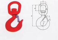
Working load limit |
Structure and size |
Weight |
322C |
322A |
B |
C |
O |
R |
S |
T |
(kg) |
0.75 |
1 |
23.81 |
31.75 |
22.23 |
127.9 |
9.53 |
20.64 |
0.77 |
1 |
1.5 |
33.34 |
38.1 |
24.61 |
134.14 |
12.7 |
20.64 |
1.27 |
1.5 |
2 |
41.27 |
44.45 |
25.4 |
152.8 |
15.88 |
21.43 |
2.28 |
2 |
3 |
36.69 |
44.45 |
28.58 |
161.925 |
15.88 |
31.16 |
2.60 |
3 |
4.5 |
44.45 |
50.8 |
34.13 |
188.12 |
19.05 |
34.93 |
4.81 |
5 |
7 |
58.74 |
53.5 |
42.86 |
243.68 |
25.4 |
45.24 |
10.40 |
7.5 |
11 |
60.33 |
69.85 |
52.39 |
382.575 |
28.58 |
53.98 |
16.42 |
10 |
15 |
71.44 |
79.38 |
37.15 |
303.21 |
31.75 |
63.5 |
23.40 |
curved hole hook
Specification |
Structure and size (mm) |
Rated load(kg) |
Weight(kg) |
C |
E |
P |
0.375 |
16 |
16 |
65.79 |
1100 |
0.77 |
0.5 |
19.05 |
19.81 |
78.49 |
1500 |
1.19 |
0.625 |
19.05 |
23.88 |
98.55 |
2300 |
2.89 |
0.75 |
25.4 |
29.46 |
115.82 |
3600 |
2.95 |
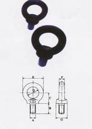
ring screw
long rings (welding )
| Rated load |
Test load |
d |
A |
B |
weight |
ton |
tTon |
mm |
mm |
mm |
Kg/pc |
1 |
2 |
Φ14 |
80 |
144 |
0.51 |
2 |
4 |
Φ18 |
80 |
144 |
0.8 |
3 |
6 |
Φ22 |
80 |
144 |
1.33 |
5 |
10 |
Φ26 |
100 |
180 |
2.20 |
8 |
16 |
Φ32 |
120 |
216 |
4.20 |
10 |
20 |
Φ35 |
120 |
216 |
5.10 |
12 |
22 |
Φ38 |
140 |
252 |
7.00 |
16 |
37 |
Φ42 |
160 |
288 |
9.70 |
20 |
32 |
Φ45 |
160 |
288 |
11.20 |
25 |
44 |
Φ52 |
180 |
324 |
16.90 |
30 |
45 |
Φ55 |
200 |
360 |
21.00 |
40 |
60 |
Φ60 |
200 |
360 |
25.00 |
50 |
75 |
Φ67 |
220 |
396 |
34.50 |
63 |
94 |
Φ72 |
220 |
396 |
40.50 |
80 |
120 |
Φ82 |
240 |
430 |
55.00 |
100 |
150 |
Φ90 |
250 |
430 |
69.50 |
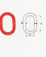
long load ( forged )
size |
Weight/kg |
WLL/T |
BL/T |
L |
W |
D |
(1/2) |
0.89 |
2.2 |
11 |
127 |
63.5 |
14 |
(5/8) |
1.63 |
3 |
15 |
152 |
76 |
16 |
(3/4) |
2.25 |
4.7 |
23.5 |
410 |
70 |
20 |
1 |
5 |
11 |
55 |
178 |
95 |
22 |
1(1/4) |
9.75 |
16 |
80 |
222 |
111 |
32 |
1(1/2) |
17.12 |
21.7 |
108.5 |
267 |
133.5 |
38 |
1(3/4) |
11.5 |
28.4 |
142 |
304.8 |
152.4 |
45 |
2 |
16.5 |
44.3 |
221.5 |
355.6 |
177.8 |
50.8 |

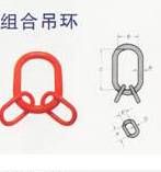
sling set
Size
(in) |
Working load
Limited(lbs.) |
Dimensions(in) |
A |
B |
C |
D |
E |
F |
(3/4) |
9100 |
0.75 |
2.75 |
5.5 |
0.47 |
0.91 |
1.66 |
1 |
18400 |
6.1 |
3.5 |
7 |
0.66 |
1.25 |
2.31 |
(1-1/4) |
31200 |
13.2 |
4.38 |
8.75 |
0.91 |
1.72 |
3.19 |
(1-1/2) |
47000 |
24.2 |
5.25 |
10.5 |
1.19 |
2.31 |
4.25 |
(1-3/4) |
73500 |
35.6 |
6 |
12 |
1.31 |
2.56 |
4.69 |
2 |
88900 |
57.3 |
7 |
14 |
1.44 |
2.75 |
5.12 |
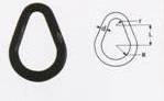
pear-shaped ring
| Rated load |
R |
r |
d |
L |
weight |
ton |
mm |
mm |
mm |
mm |
Kg/pc |
3 |
60 |
20 |
20 |
85 |
1.24 |
5 |
65 |
25 |
30 |
93 |
3.22 |
8 |
75 |
30 |
33 |
100 |
4.39 |
10 |
80 |
50 |
38 |
146 |
7.35 |
16 |
80 |
50 |
45 |
146 |
10.59 |
round rings
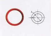
| Rated load |
R |
L |
Weight |
ton |
mm |
mm |
Kg/pc |
3 |
24 |
100 |
2.77 |
5 |
28 |
150 |
5.40 |
8 |
33 |
175 |
8.77 |
10 |
38 |
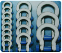
225 |
14.71 |
16 |
45 |
225 |
21.18 |
20 |
52 |
250 |
31.63 |
25 |
58 |
315 |
48.61 |
west Germany ringer
type |
F |
C |
A |
B |
L |
D |
E |
weight |
in |
mm |
mm |
mm |
mm |
mm |
mm |
mm |
Kg/100pcs |
8 |
8.6 |
14 |
20 |
40 |
56 |
5 |
20 |
8 |
10 |
10.8 |
17 |
25 |
50 |
70 |
5 |
20 |
17 |
12 |
12.9 |
21 |
30 |
60 |
84 |
5 |
20 |
32 |
14 |
15.1 |
24 |
35 |
70 |
98 |
5 |
20 |
50 |
16 |
17.2 |
28 |
40 |
80 |
112 |
5 |
20 |
78 |
18 |
19.4 |
31 |
45 |
90 |
126 |
5 |
20 |
114 |
20 |
21.5 |
35 |
50 |
100 |
140 |
10 |
30 |
141 |
22 |
23.7 |
38 |
55 |
110 |
154 |
10 |
30 |
196 |
24 |
25.8 |
42 |
60 |
120 |
168 |
10 |
30 |
241 |
26 |
28.0 |
45 |
65 |
130 |
182 |
10 |
30 |
346 |
28 |
30.1 |
49 |
70 |
140 |
196 |
10 |
30 |
430 |
30 |
34.4 |
56 |
80 |
160 |
224 |
10 |
30 |
646 |
36 |
38.7 |
63 |
90 |
180 |
252 |
10 |
30 |
977 |
40 |
43.0 |
70 |
100 |
200 |
280 |
10 |
30 |
1294 |
44 |
47.3 |
77 |
110 |
220 |
308 |
15 |
45 |
1702 |
48 |
51.6 |
84 |
120 |
240 |
336 |
15 |
45 |
2275 |
50 |
55.9 |
91 |
130 |
260 |
364 |
15 |
45 |
2841 |
56 |
60.2 |
98 |
140 |
280 |
392 |
15 |
45 |
3556 |
60 |
64.5 |
105 |
150 |
300 |
420 |
15 |
45 |
4835 |
heavy ringer
rope wedge connector
nominal metric size of
wedge-shaped joints
(mm) |
Rated load
KN |
Breaking load
KN |
B
mm |
D
(H10)
mm |
A
mm |
R
mm |
Opening
pin |
Weight
Kg/pc |
6 |
10 |
43 |
29 |
16 |
90 |
16 |
2×20 |
0.56 |
83 |
10 |
51 |
31 |
18 |
100 |
25 |
2×20 |
0.77 |
10 |
15 |
71 |
38 |
20 |
120 |
25 |
2×25 |
1.01 |
12 |
20 |
100 |
44 |
25 |
155 |
30 |
2×25 |
1.70 |
14 |
25 |
118.5 |
51 |
30 |
185 |
35 |
2×25 |
2.34 |
16 |
30 |
161.3 |
60 |
34 |
195 |
42 |
3×30 |
3.27 |
18 |
35 |
184.0 |
64 |
36 |
195 |
44 |
3×30 |
4.00 |
20 |
50 |
249.6 |
72 |
38 |
220 |
50 |
3×30 |
5.45 |
22 |
55 |
285.3 |
76 |
40 |
240 |
52 |
4×50 |
6.37 |
24 |
65 |
327.0 |
83 |
50 |
260 |
60 |
4×50 |
8.32 |
26 |
75 |
373.6 |
92 |
55 |
280 |
65 |
4×50 |
10.16 |
28 |
95 |
487.6 |
97 |
55 |
305 |
70 |
4×50 |
13.94 |
32 |
120 |
600 |
110 |
65 |
360 |
77 |
5×60 |
17.94 |
36 |
155 |
780 |
122 |
70 |
390 |
85 |
5×60 |
23.03 |
40 |
200 |
984 |
145 |
75 |
470 |
90 |
5×60 |
32.35 |
chain connector
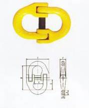
Art.no |
Suitable chain |
A |
B |
C |
D |
E |
F |
G |
Self-weight |
t |
mm |
mm |
mm |
mm |
mm |
mm |
mm |
kg |
HDH6 |
6 |
9 |
48 |
21 |
7 |
50 |
12 |
20.5 |
0.09 |
HDH8 |
8 |
11 |
58 |
21 |
9 |
54 |
14 |
24.5 |
0.17 |
HDH10 |
10 |
14 |
74 |
27 |
12 |
68 |
18 |
31.5 |
0.39 |
HDH12 |
12 |
17.5 |
94 |
37 |
13.5 |
88 |
20 |
41 |
0.64 |
HDH14 |
14 |
20 |
106 |
41 |
16 |
98 |
28 |
45.5 |
1.11 |
HDH16 |
16 |
23 |
114 |
45 |
18 |
110 |
30 |
48.5 |
1.55 |
HDH18 |
18 |
25 |
124 |
48 |
20 |
120 |
34 |
52.5 |
2.01 |
HDH20 |
20 |
28 |
131 |
50 |
23 |
130 |
36 |
55 |
2.67 |
HDH22 |
22 |
30 |
138 |
53 |
25 |
140 |
41 |
57.5 |
3.58 |
HDH24 |
24 |
33 |
150 |
59 |
27 |
152 |
45 |
62.5 |
4.70 |
HDH26 |
26 |
37 |
166 |
63 |
30 |
51 |
47 |
70 |
5.76 |
HDH30 |
30 |
40 |
180 |
65 |
33 |
170 |
50 |
7605 |
6.84 |
HDH34 |
34 |
42 |
190 |
73 |
34 |
206 |
54 |
80 |
8.74 |
chain adjuster
Working load limit |
Chain size |
figure dimensions(mm) |
T |
mm |
A、B |
C |
D |
E |
F |
1.1 |
6 |
6.7 |
8 |
7 |
11 |
45 |
2 |
7.8 |
8.7 |
10 |
9 |
16 |
62 |
3.2 |
10 |
12.5 |
14 |
12 |
25 |
87 |
5.4 |
13 |
16.5 |
17 |
15 |
32 |
115 |
8 |
16 |
20.5 |
19 |
19 |
39 |
143 |
12.5 |
18、20 |
21.5 |
23 |
22 |
46 |
152 |
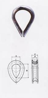
casted joint (closed )
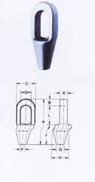
rope diameter |
A |
B |
C |
D |
F |
G |
H |
J |
K |
L |
B |
In |
mm |
mm |
mm |
mm |
mm |
mm |
mm |
mm |
mm |
mm |
mm |
1/4 |
114 |
13 |
40 |
22 |
10 |
18 |
40 |
57 |
13 |
44 |
0.23 |
5/16-3/8 |
124 |
16 |
43 |
25 |
13 |
21 |
43 |
57 |
18 |
51 |
0.34 |
7/16-1/2 |
138 |
18 |
51 |
30 |
15 |
24 |
51 |
63 |
22 |
57 |
0.68 |
9/16-5/8 |
160 |
21 |
67 |
36 |
18 |
28 |
67 |
76 |
25 |
63 |
1.13 |
3/4 |
193 |
27 |
76 |
42 |
21 |
32 |
76 |
90 |
32 |
76 |
1.90 |
7/8 |
223 |
32 |
92 |
48 |
24 |
38 |
92 |
102 |
38 |
89 |
3.30 |
1 |
250 |
35 |
105 |
58 |
29 |
44 |
105 |
113 |
44 |
102 |
4.80 |
11/8 |
279 |
38 |
114 |
65 |
32 |
51 |
114 |
127 |
51 |
114 |
6.50 |
11/4-13/8 |
308 |
41 |
135 |
71 |
38 |
57 |
135 |
140 |
57 |
127 |
9.00 |
11/2 |
354 |
50 |
135 |
81 |
41 |
70 |
135 |
152 |
64 |
152 |
13.30 |
15/8 |
384 |
54 |
146 |
83 |
44 |
76 |
146 |
165 |
70 |
165 |
16.30 |
13/4-17/8 |
439 |
56 |
171 |
95 |
51 |
80 |
171 |
191 |
76 |
192 |
26.00 |
2-21/8 |
495 |
62 |
194 |
111 |
57 |
95 |
194 |
216 |
83 |
217 |
35.80 |
21/4-23-8 |
537 |
67 |
216 |
127 |
64 |
102 |
216 |
229 |
92 |
241 |
47.60 |
21/2-25-8 |
597 |
79 |
241 |
140 |
73 |
114 |
241 |
248 |
102 |
270 |
63.50 |
23/4-27/8 |
644 |
79 |
273 |
159 |
79 |
124 |
273 |
279 |
124 |
286 |
99.80 |
3-31/8 |
686 |
83 |
292 |
171 |
86 |
133 |
292 |
305 |
133 |
298 |
125.20 |
31/4-33/8 |
743 |
102 |
311 |
184 |
92 |
146 |
311 |
330 |
146 |
311 |
142.00 |
31/2-35/8 |
788 |
102 |
330 |
197 |
99 |
165 |
330 |
356 |
159 |
330 |
181.40 |
33/4-4 |
845 |
108 |
362 |
216 |
108 |
184 |
362 |
381 |
178 |
356 |
245.90 |
casted joint (open )
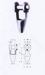
rope diameter |
A |
B |
C |
D |
G |
H |
J |
L |
M |
N |
B |
In |
mm |
mm |
mm |
mm |
mm |
mm |
mm |
mm |
mm |
mm |
mm |
1/4 |
116 |
23 |
17 |
10 |
18 |
41 |
57 |
40 |
33 |
9 |
0.50 |
5/16-3/8 |
123 |
21 |
21 |
13 |
21 |
43 |
57 |
44 |
38 |
11 |
0.60 |
7/16-1/2 |
142 |
25 |
25 |
15 |
24 |
51 |
64 |
51 |
48 |
13 |
1.00 |
9/16-5/8 |
172 |
32 |
30 |
18 |
28 |
60 |
76 |
64 |
57 |
14 |
1.60 |
3/4 |
202 |
38 |
35 |
21 |
32 |
70 |
89 |
76 |
67 |
16 |
2.60 |
7/8 |
235 |
44 |
41 |
24 |
38 |
84 |
102 |
89 |
80 |
20 |
4.40 |
1 |
269 |
51 |
51 |
29 |
44 |
95 |
114 |
102 |
95 |
22 |
7.00 |
11/8 |
303 |
57 |
57 |
32 |
51 |
107 |
127 |
117 |
105 |
25 |
9.80 |
11/4-13/8 |
335 |
64 |
64 |
38 |
57 |
122 |
140 |
127 |
121 |
29 |
14.10 |
11/2 |
384 |
76 |
70 |
41 |
70 |
136 |
152 |
152 |
137 |
30 |
21.40 |
15/8 |
412 |
76 |
76 |
44 |
76 |
142 |
165 |
165 |
146 |
33 |
25.00 |
13/4-17/8 |
464 |
89 |
89 |
51 |
80 |
169 |
191 |
178 |
165 |
40 |
37.20 |
2-21/8 |
545 |
102 |
95 |
57 |
95 |
194 |
228 |
228 |
178 |
46 |
58.50 |
21/4-23-8 |
606 |
114 |
108 |
64 |
102 |
222 |
254 |
254 |
197 |
54 |
75.80 |
21/2-25-8 |
654 |
127 |
121 |
73 |
114 |
247 |
273 |
173 |
215 |
60 |
114.30 |
23/4-27/8 |
692 |
133 |
127 |
79 |
124 |
279 |
279 |
279 |
229 |
73 |
142.90 |
3-31/8 |
737 |
146 |
133 |
86 |
133 |
298 |
305 |
286 |
241 |
76 |
172.40 |
31/4-33/8 |
784 |
159 |
140 |
92 |
146 |
317 |
328 |
298 |
254 |
79 |
196.90 |
31/2-35/8 |
845 |
172 |
152 |
99 |
165 |
338 |
360 |
318 |
273 |
83 |
255.40 |
33/4-4 |
921 |
191 |
178 |
108 |
184 |
369 |
389 |
343 |
318 |
89 |
355.20 |
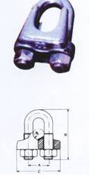
wire rope clip(A)
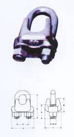
type |
A |
B |
C |
D |
E |
F |
G |
weight |
mm |
mm |
mm |
mm |
mm |
mm |
mm |
mm |
Kg/100pcs |
6 |
22.5 |
14 |
17 |
5 |
14 |
14 |
24.8 |
2.5 |
8 |
28 |
17 |
21 |
6 |
15 |
16 |
30.7 |
4.5 |
10 |
38 |
21 |
28 |
8 |
19 |
20 |
38.0 |
9.0 |
12 |
45 |
27 |
34 |
10 |
24 |
25 |
47.6 |
18 |
15 |
52 |
32 |
40 |
12 |
29 |
30 |
57.2 |
28 |
20 |
62 |
38 |
46.5 |
14 |
36 |
36 |
71.7 |
48 |
22 |
69 |
43 |
51.5 |
16 |
40 |
39 |
78.7 |
62 |
25 |
76 |
50 |
56 |
18 |
43 |
44 |
90.4 |
85 |
28 |
85 |
57 |
62 |
20 |
48 |
48 |
96.9 |
120 |
32 |
93 |
61 |
67 |
22 |
55 |
51 |
110.4 |
156 |
40 |
111 |
73 |
81 |
24 |
64 |
62 |
122.5 |
262 |
45 |
123 |
86 |
88 |
27 |
72 |
70 |
139.5 |
360 |
50 |
135 |
95 |
95 |
30 |
80 |
88 |
156.0 |
480 |
wire rope clip
Type |
A |
B |
C |
D |
E |
weight |
mm |
mm |
mm |
mm |
mm |
mm |
Kg/100pcs |
6 |
14 |
35 |
8 |
M6 |
5 |
4 |
8 |
18 |
44 |
10 |
M8 |
6 |
8 |
10 |
22 |
55 |
13 |
M10 |
8 |
18 |
12 |
28 |
69 |
16 |
M12 |
10 |
26 |
15 |
33 |
83 |
19 |
M14 |
11 |
36 |
20 |
39 |
96 |
22 |
M16 |
13 |
50 |
22 |
44 |
108 |
24 |
M18 |
14 |
70 |
25 |
49 |
122 |
27 |
M20 |
16 |
120 |
28 |
55 |
137 |
31 |
M22 |
18 |
150 |
32 |
60 |
149 |
33 |
M24 |
19 |
210 |
40 |
67 |
164 |
35 |
M26 |
19 |
260 |
45 |
78 |
188 |
40 |
M28 |
22 |
420 |
50 |
88 |
210 |
44 |
M30 |
24 |
560 |
Turnbuckle
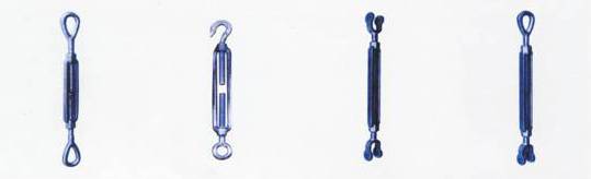
turnbuckle
(USA.OO) |
|
turnbuckle
(USA. CO) |
|
turnbuckle
(USA.UU) |
|
turnbuckle
(USA .OU) |
TYPE |
Rated load |
weight |
|
TYPE |
Rated load |
weight |
|
TYPE |
Rated load |
weight |
|
TYPE |
Rated load |
weight |
In |
Kg |
Kg |
|
In |
Kg |
Kg |
|
In |
Kg |
Kg |
|
In |
Kg |
Kg |
5/8×6 |
1587.58 |
1.28 |
|
5/8×6 |
1020.58 |
1.22 |
|
5/8×9 |
1587.58 |
1.56 |
|
5/8×9 |
1587.58 |
1.56 |
5/8×9 |
1587.58 |
1.49 |
|
5/8×9 |
1020.58 |
1.41 |
|
5/8×12 |
1587.58 |
1.77 |
|
5/8×12 |
1587.58 |
1.77 |
5/8×12 |
1587.58 |
1.55 |
|
5/8×12 |
1020.58 |
1.71 |
|
3/4×6 |
2358.68 |
1.86 |
|
3/4×6 |
2358.68 |
1.86 |
3/4×6 |
2358.68 |
1.72 |
|
3/4×6 |
1360.77 |
1.76 |
|
3/4×9 |
2358.68 |
2.48 |
|
3/4×9 |
2358.68 |
2.48 |
3/4×9 |
2358.68 |
2.09 |
|
3/4×9 |
1360.77 |
2.09 |
|
3/4×12 |
2358.68 |
2.92 |
|
3/4×12 |
2358.68 |
2.92 |
3/4×12 |
2358.68 |
2.49 |
|
3/4×12 |
1360.77 |
2.64 |
|
3/4×18 |
2358.68 |
3.66 |
|
3/4×18 |
2358.68 |
3.66 |
3/4×18 |
2358.68 |
3.26 |
|
3/4×18 |
1360.77 |
2.87 |
|
7/8×12 |
3265.87 |
3.71 |
|
7/8×12 |
3265.87 |
3.71 |
7/8×12 |
3265.87 |
3.27 |
|
7/8×12 |
1814.37 |
3.67 |
|
7/8×18 |
3265.87 |
4.89 |
|
7/8×18 |
3265.87 |
4.89 |
7/8×18 |
3265.87 |
4.51 |
|
7/8×18 |
1814.37 |
4.51 |
|
1×6 |
4535.92 |
4.62 |
|
1×6 |
4535.92 |
4.62 |
1×6 |
4535.92 |
4.10 |
|
1×6 |
2267.96 |
4.23 |
|
1×12 |
4535.92 |
5.68 |
|
1×12 |
4535.92 |
5.68 |
1×12 |
4535.92 |
5.21 |
|
1×12 |
2267.96 |
5.41 |
|
1×18 |
4535.92 |
6.87 |
|
1×18 |
4535.92 |
6.87 |
1×18 |
4535.92 |
6.35 |
|
1×18 |
2267.96 |
6.35 |
|
1×24 |
4535.92 |
8.20 |
|
1×24 |
4535.92 |
8.20 |
1×24 |
4535.92 |
7.82 |
|
1×24 |
2267.96 |
7.82 |
|
11/4×12 |
6894.61 |
9.34 |
|
11/4×12 |
6894.61 |
9.34 |
11/4×12 |
6894.61 |
9.62 |
|
11/4×12 |
2948.35 |
8.61 |
|
11/4×18 |
6894.61 |
11.19 |
|
11/4×18 |
6894.61 |
11.19 |
11/4×18 |
6894.61 |
10.43 |
|
11/4×18 |
2948.35 |
10.43 |
|
11/4×24 |
6894.61 |
12.29 |
|
11/4×24 |
6894.61 |
12.29 |
11/4×24 |
6894.61 |
12.25 |
|
11/4×24 |
2948.35 |
10.88 |
|
|
|
|
|
|
|
|
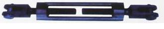
special type turnbuckle
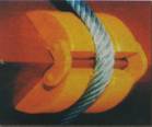
Moving pads
Apply to steel wire rope sling , chain rigging sling , soft sling , flat sling , rope and other lifting
equipment .
Effectively reduced the friction between the objects and sling
Effectively protected the lifting objects and extended the life of the lifting sling.
Automatic adsorption device attached to the object edges and corners when lifting iron , convent in using.
product pictures |

|
wire rope pads |
lifting belt pads |

|
|
|
|